Posts: 236
Threads: 26
Joined: Mar 2020
Reputation:
29
Gimp version:
Operating system(s): Windows (Vista and later)
Hello again!
I have three plugins to share. They are about transformations of Gimp's paths. Nothing remarkable. They are the first step in my current project, and I paused my work to make them into plugins. My long-range aim is to try to make plugins that transform Gimp paths by certain more interesting (conformal) maps.
I know that there are already transformations to deform images. At least G'MIC has a long list. I have not tried those, but it is my guess that they transform images, not paths. But if I am wrong, and if they (or some other existing plugin) can be applied to paths, I hope that somebody tells me so that I shall not work in vain. The problem in transforming a path (for example by a Möbius transformation or such) is different from transforming an image since the input is control points of Bézier curves and the result must again be represented as Bézier curves. Hence, there needs to be an approximation.
Anyway, as a preliminary step I wrote the three plugins. These plugins deal with cases where no approximation is needed, so the results are exact.
Of each of the three plugins I shall soon make a special introductory post. My time is nowadays rather limited, and I think this will take perhaps a week. Here is a quick overview of the plugins:
1. Affine maps. Nothing new here, of course, since Gimp's own transformation tools do affine maps on paths. My plugin gives a different interface: not WYSIWYG, no moving of points on the screen with the mouse, nothing fancy. Very elementary, and the reason why I made the plugin is that I may need affine maps later in my project, and certainly I need similarity maps.
2. Transforming a line figure by a transformation constructed from a Bézier arc. This is new, to me at least. The path to be transformed is what I call a line figure: a path consisting of straight line segments (for example a lattice or a grid). The transformation is in a certain manner constructed from a user-supplied Bézier arc (a path with two anchors). A different arc will give a different transformation. This all I shall explain in detail in a later post.
A3. Deforming a polyline, segment by segment, with a transformation as in number 2. (Actually I call the deforming "curling".) Number 3 is just a variation of number 2.
Of the three I expect number 2 to be the only one interesting. (But then when I ever try to guess what people will find interesting, I go astray. Perhaps I should only say that to me number 2 is the only interesting.) What I myself have in mind is that the code of this plugin will serve as the body where I shall add an approximation algorithm (don't know yet how). Number 1 does nothing new, and number 3 is ..., well, I doubt if it is worth publishing after all, and perhaps it will be removed in later versions.
To get the plugins, go to
http://kmarkku.arkku.net/Path_transforma...aster.html
and scroll down to the bottom. There is a Download button, and it gives you a .zip file containing one file path_transformations.py. Put the .py file in your Gimp's plug-ins folder and restart Gimp. That registers three plugins in your Gimp. They can be invoked in Gimp's Paths tab: right-click the path you want to transform, and at the bottom of the opening window follow
Tools > Transformations > ...
and you will see three plugins to choose from. You can try them right away, but I am going to make explanatory posts of each soon. For the affine maps it will appear today. The rest will follow in a week.
Posts: 236
Threads: 26
Joined: Mar 2020
Reputation:
29
Gimp version:
Operating system(s): Windows (Vista and later)
In post #1 I explained how to get the three plugins. Now I talk about the one called
Transform a path by an affine map
The plugin performs an affine mapping. (Nothing new there; Gimp's standard tools do the same.) To define the map, you must provide two auxiliary paths; I call them the Base and the Target. I show a picture:
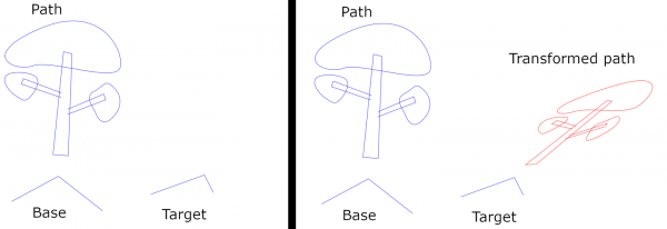
On the left are the original input paths. The Path is the path to be transformed. The Base and the Target are two three-anchor paths. They define the affine map: It is the map which sends the three anchors of the Base to the three anchors of the Target. On the right is the result. (The example also shows my artistic level.)
If you happen to draw the Base and the Target in the wrong way, one from the left to the right and the other in the opposite direction and if that was not intentional, you can make the plugin to use the reversed version of the Base.
This all is very basic. An affine map does nothing very dramatic. One case where this plugin may be nicer to use than the standard tools, is if you need to transform several paths by the same affine map: you can use the same Base and Target repeatedly.
In the example above, the Base has three anchors. You can instead use a path with two or one anchors. If it has two anchors, the map will be a direct similitude (mapping the Base to the Target). If there is only one anchor, the map will be a translation. The Target, on the other hand, must have at least as many anchors as the Base has.
Posts: 236
Threads: 26
Joined: Mar 2020
Reputation:
29
Gimp version:
Operating system(s): Windows (Vista and later)
I updated the plugin to version 0.6. Please take the new version from the same place I mentioned in post #1.
I continue talking of the plugins (see posts #1 and #2). Now the second plugin,
Transform a line figure by a Bezier arc
How to get it and how to invoke it, see the bottom of post #1. This plugin is supposed to be applied only to paths consisting of straight line segments; I call those "line figures". (You can apply it to any paths but only anchors are taken into account, so that the edges between anchors are treated as straight line segments.)
To use the plugin you have to provide four input paths:
1. The Line figure: the path to be transformed (by right-clicking in Gimp's Paths tab).
2. The Base: a path with two anchors.
3. The Target: a path with two anchors.
4. the Shaper: a path with two anchors.
Of the first three input paths only the anchors are taken into account; any curviness is ignored. The Shaper, on the contrary, is supposed to be a proper arching curve: it will determine the "shape" of the transformation, that is, how the transformation will curve line segments.
Just as for the affine maps, the anchors of the Base will be mapped to the anchors of the Target. The position of the Shaper has no effect, only the shape.
It is easiest to give a picture:
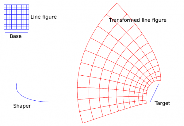
You see the four input paths (in blue). The Line figure is the small grid at top left. The transformation deformes the grid and puts it at a different location; the result is shown in red. Notice that right angles are preserved. This is no coincidence - the transformation is conformal! (Or, to be precise, is when some special cases are excluded.) It is unfortunate that the plugin works only with paths made of straight line segments. It is my hope to remove that restriction some day.
I attach here the .xcf file in case somebody wants to do experiments with the plugin. I hope you will enjoy.
 linefigure_by_bezier.xcf
 (Size: 34.15 KB / Downloads: 492)
When you try the plugin, be sure to choose the right paths as the Line figure, the Base, the Target, and the Shaper. If you modify the Shaper, please try first with only tiny changes. The result will easily become very wild. The reason is that the plugin is based on a polynomial map of degree 3 (coming from the Shaper) on the complex plane, and it is unwieldy. You can easily make the image to overlap itself. To predict the results is in practice not possible(?), so one just has to experiment. But the plugin has the input "Strength of shaping", default value is 1, and lowering its value will help. In effect, setting it closer to 0 will flatten the Shaper.
You may experiment with different Bases. You may even use the Line figure itself as the Base. In that case the plugin will use the first two anchors of the first stroke, and in this picture it happens to be the top edge of the grid from the left to the right. (In this picture, setting at the same time Base to 'reversed' gives a nicer result.)
In the new version 0.6 I added two float arguments A and B to tweak the result. Default is A=0, B=1. Here is what happens when A=1, B=2, otherwise the inputs are as above:
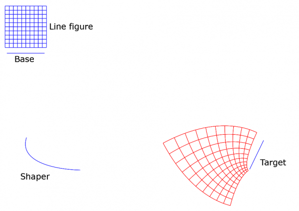
Again, it is not possible to predict the outcome of different tweakings. Too complicated. The only way is to do experiments.
Sorry about the long post. You can safely skip the rest if mathematics is not in your line. I want to explain the mathematical idea behind the transformation. It is my own idea, but of course I am hardly the first one to get this simple idea. But I don't remember having seen it anywhere. When you have understood it once, you'll agree that it is rather obvious but nevertheless a nice idea.
I tried first to write the explanation in ASCII but abandoned soon the effort and just used LaTeX to make a small .pdf. It is attached here:
 transformation_by_bezier.pdf
 (Size: 84.62 KB / Downloads: 601)
When I first got the idea of this transformation (must be almost two years ago) and realized that it is conformal and sends straight lines to Bézier curves, I became really curious to see in a concrete way what the map would look like. That means making drawings on the screen. With this plugin I can do it now.
Some words about the new tweakings A and B: The way I first implemented the plugin, it had the following special property (and still has when A=0, B=1): If the Base happens to be a part of the Line figure, the image of the Base will be a similar copy of the Shaper. This may be a nice feature. It just dawned on me yesterday that if we dispense with that similarity condition, we have plenty of other transformations and much richer choice of equally nice figures, as I soon noticed by experimenting. In the new version 0.6 it goes like this (if I understand it right): With the tweaking inputs A and B, instead of the Shaper the plugin uses another arc of the same infinite Bézier curve (of which the Shaper is a segment), namely the arc between parameter values t=A and t=B. The image of the Base is then similar to that arc.
Posts: 134
Threads: 15
Joined: Apr 2017
Reputation:
6
Gimp version:
Operating system(s): Linux
Very interesting plug-ins, will definitely be using these. Thank you!
Posts: 236
Threads: 26
Joined: Mar 2020
Reputation:
29
Gimp version:
Operating system(s): Windows (Vista and later)
Really nice to hear that somebody got interested.
I continue talking of the plugins (see posts #1 and #2). Now the third plugin,
Curl a polyline by a Bezier arc
This plugin is just an afterthought to the previous plugin, but it may be to some use. How to get it, see post #1.
This plugin is meant to be applied to paths consisting of straight line segments. I call such paths now "polylines" (rather than "line figures") because of how they are treated now. The plugin "curls" the line segments one by one. (That term "curling" is another difficult choice but I didn't find any better. Suggestions are welcome.)
The crucial aspect where this plugin differs from the previous one (post #3) is that instead of transforming a line figure by one global transformation, this plugin transforms each line segment separately and keeps the nodes fixed. So, instead of one global transformation there is a series of local transformations.
To use the plugin you have to input two paths:
1. The Polyline: the path to be transformed (by right-clicking in Gimp's Paths tab).
2. The Shaper: a path with two anchors.
Of the polyline only the anchors are taken into account.
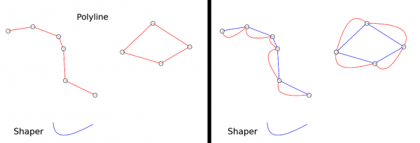
On the left you see the original Polyline and Shaper. On the right (red curve) is what the plugin does with default settings. It produces a copy of the Polyline where the line segments are replaced by copies of the Shaper.
The plugin allows setting "strength of curling". Default is 1; the effect you see above. If the strength is 0, there will be no curling and the line segments remain visually untouched (though the handles are changed).
But the plugin allows also a list as the input for the strength. Inputting list .25, .5, .75, 1 you get what is on the left below:
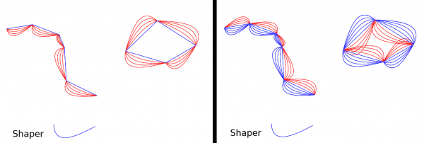
There are several ways to input the list: either .25, .5, .75, 1 (numbers separated by commas), or (.25, .5, .75, 1) or [.25, .5, .75, 1] (Python tuple or list), or even [(k+1)*.25 for k in range(4)] (Python list).
The plugin allows to use the Shaper as reversed version. On the right is shown together in the same picture (1) the above result; (2) the same made with the Shaper reversed; and (3) the original Polyline.
Finally, there is some kind of a smoothing option. With it one can change the corners to smooth nodes. Since I don't know any good way to characterize the shape of a smooth corner (for example, one way would be to give handle directions and lengths, but that is hardly practical in the GUI), I didn't equip the plugin with any method to control the shape of the smoothing. Only one possible choice is implemented. I suggest you just experiment to see what smoothing does. And note that setting strength of curling to 0 and strength of smoothing to 1, you get smoothing of the original polyline without the Shaper being involved in any way.
Posts: 236
Threads: 26
Joined: Mar 2020
Reputation:
29
Gimp version:
Operating system(s): Windows (Vista and later)
Hello!
I have updated the plugins to version 0.9. The link is in post #1. Three essential changes were made:
1. I decided to drop the plugin "Curl a polyline by a Bezier arc", see post #5. It does not fit among the other path transformation plugins, those present now and those I plan to make soon. And honestly, I don't expect anybody to miss it. (But if somebody wants it, I can return it but give it a different place in Gimp's menu.)
2. I managed to include an approximation algorithm, so that now we have a plugin which handles any paths, not only line figures consisting of straight line segments.
3. The previous plugin "Transform a line figure by a Bezier arc" (post #3) is no more a separate plugin but is included as one option in the new plugin.
So, if you go to the link in post #1, fetch the new .ZIP file, unzip it, put it in Gimp's plug-ins folder (replacing the older path_transformations.py), and restart Gimp, you will have two plugins to do transformations on paths:
Transform a path by an affine map
Transform a path by a Bezier arc
They are found in Gimp by going to the Paths tab and right-clicking the path you want to transform, and following the links Tools > Transformations > ...
For the first plugin (affine map), see post #2; I don't explain it here.
Let us look at the second plugin Transform a path by a Bezier arc. First, you can use it just as before on line figures by clicking in the GUI the first Boolean field to Yes. That causes the plugin to ignore of the path everything except the anchors. That case the plugin can handle exactly. But if you keep the field as No (the default), the plugin applies to any curving path and tries its best to deal with the curvatures correctly. That involves approximation, which means that the plugin is somewhat slow (patience, please!) and that the results are not quite exact.
Now pictures: The first picture shows the already familiar line figure case. On the left there is the setup: the three paths Base, Target, and Shaper. On the right is a line figure (blue) and its image in the transformation (red).

The second picture shows the new effect of the plugin: transformation of a curving path. On the left is a path (outlines of six letters, blue) and its image in the transformation (red). On the right is the same job for a path 'rhodonea' which I drew with an older plugin of mine.

I include also a .xcf file where all these ingredients are present, with the purpose that you will have it easier to experiment. It contains now quite a lot of paths, so that when you invoke the plugin, be careful that you choose the right paths for the Base, the Target, and the Shaper (and of course the path you want to transform).
 path_bezier.xcf
 (Size: 55.24 KB / Downloads: 529)
The GUI of the plugin offers now a new choice: The user can choose the algorithm to be used; either good and slow; or bad and fast. The idea is that one can first force the plugin to use a simple algorithm which is quick but inaccurate. This enables one to do experiments with the quick algorithm (which may also put excessively many anchors), and when one has found what one likes, then the plugin can be run with the good but slow algorithm which hopefully also keeps the number of anchors low.
The choice of the algorithm is controlled by one input number which is a non-negative integer. Default is 0 (the full algorithm). Inputs 1,2,3,... give the simple algorithm, and the larger the number, the more accurate the result will be but with ever increasing number of control points. I don't expect there is any need to go over 5, but of course one can try. The simple algorithm is so fast that you can go higher, if only the large number of anchors does not bother you.
As for the anchors, the transformed path will always have those anchors that correspond to the anchors of the original path, and extra anchors will be created to get better approximation. (This also means that if you suspect that the result is not accurate enough, you can try to add anchors to the original path at critical points.)
What makes the plugin slow, is the approximation. The algorithm is my own and would certainly need much development, and everything is written in Python. I am very much aware of that my approximation algorithm is rather rickety and occasionally fails. When that happens, the plugin resorts to recursion, putting anchors more densely and hoping for the best.
If you have any problems with the plugins, please let me know. This is work in progress, and any feedback will be valuable.
Posts: 236
Threads: 26
Joined: Mar 2020
Reputation:
29
Gimp version:
Operating system(s): Windows (Vista and later)
I have updated the plugins to version 0.12. The link is in post #1. The .ZIP file contains everything. What is new is the Möbius transformation. Actually there are four plugins to perform a Möbius mapping. The main one will be found in Gimp's menu (after right-clicking the path you want to transform) at
Tools > Transformations > Moebius map
and then there are three more at
Tools > Transformations > Moebius map with control of poles > ...
In this post I talk about the first one. Later I shall make a separate post about the other three.
I stress the fact that in some cases the plugin may be so slow that the user wants to interrupt it. Therefore, one had better know how to stop it without stopping Gimp (in Windows 10 it is the Task Manager), and in any case it is good to save one's work before trying the plugin. In practice, it may be wise to experiment first using the simple algorithm (see below), and only when one has found what one likes, to realize it with the good but slow algorithm.
For mathematical background on the Möbius map, you can look at
https://en.wikipedia.org/wiki/M%C3%B6biu...sformation
I list here only the most crucial features of Möbius maps:
- A Möbius map is actually a transformation on the extended plane (=plane + a point at infinity). For simplicity, I side-step now infinities altogether (postponed to the next post).
- Given any triple A,B,C of distinct points and another triple X,Y,Z of distinct points, there is precisely one Möbius map sending A->X, B->Y, and C->Z.
- A Möbius map is conformal: all angles are preserved.
- Circular arcs are sent to circular arcs.
- But here "circles" include straight lines, since a straight line is viewed as an infinite circle. (Ok, here the infinity comes in after all!) Therefore, the image of any straight line segment will be a circular arc (or in rare cases another line segment).
From the user's point of view, the main differences from the older plugin doing the transformation constructed from a Bezier arc (post #3) are:
- No Shaper is used.
- The Base and the Target are paths with three anchors each. These will give the points A,B,C and X,Y,Z.
- Line segments are normally sent to circular arcs (rather than to copies of a Shaper).
- The plugin offers an easy way to use the 3 anchors of the Base in any of their 6 permutations.
- And then there is the infinity which may cause surprises. But about that in another post.
In the following picture on the left I show what the Base and the Target might look like. They are three-anchor paths; only the anchors are taken into account, and all curviness is ignored.
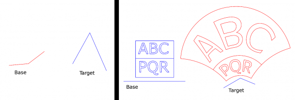
On the right you see what the plugin does in practice. Here I used a straight Base and a slightly bending Target. The path to be transformed (blue) is the letters ABCPQR "framed" by straight edges. The result is shown in red in the same picture. Note that the straight edges are mapped onto circular arcs.
In the next picture below, on the left is a figure consisting of three astroids (blue, drawn by means of my Parametric curves plugin) and the transformed path (red). Again I used a straight Base.
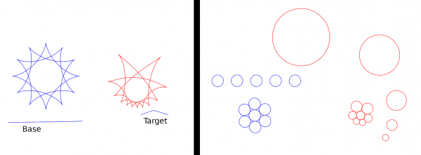
On the right I want to show that circles are indeed sent to circles. The Base (straight) and the Target are there but set to unvisible in this picture. The original path is the blue set of 12 circles, and the transformed path is the red circles. You see that the circles are indeed sent to circles. Note also that the five blue circles in a straight row are sent to circles of increasing sizes which (just believe it!) have their centers on another circle.
(By the way, to create the original circles I used the Parametric curves plugin and Gimp's copying and moving tools.)
Just as in post #6, the plugin offers the choice of the algorithm. Input 0 gives the good but slooow algorithm. Inputs 1,2,... invoke a simple algorithm, quick but inaccurate. Higher number means better accuracy but with the cost of increasing number of control points. The behaviour differs now from the previous version in that the number of control points grows exponentially with the input number. For that reason the plugin forces the input number to <=8. I expect that in practice 2..5 will suffice, depending on the case.
If you have any problems with the plugins, please let me know. It has become so complicated that it seems that almost every time when I think it is ready to be published, and I am just making example pictures, the plugin fails somehow. Then I just have go back to the code to find out what I have overlooked this time. Every case where the plugin fails is invaluable for finding bugs, so please report.
Posts: 236
Threads: 26
Joined: Mar 2020
Reputation:
29
Gimp version:
Operating system(s): Windows (Vista and later)
When you apply the Möbius map plugin, it sometimes tells that it "hit an infinity" and stops without result. That means that it tried to calculate a value of the Möbius function which turned out to be infinite.
Infinities belong naturally to the framework where the Möbius map lives. As I said before, the Möbius map really is a transformation on the extended plane. Mathematically, there is one "point at infinity", and it is nothing special. It is treated just as any one point among all the other, "normal" points.
But when we are drawing something concretely on the screen, infinities are a problem, as are any very distant points. Given a Möbius map, there are normally two special points: the "pole" and the "inverse pole".
- The pole is the point which the Möbius function sends to infinity (M(z)=infinite).
- The inverse pole is the point to which the infinite point is sent by the Möbius function. (The term "inverse pole" I took from the Wikipedia page, and I don't know any better name for it. The inverse pole is the pole of the inverse Möbius map.)
The pole is more significant to us, and I talk now mainly only about that.
The pole is sent to infinity, and the plugin cannot handle such value. So, if the pole happens to be contained in the input path (the path to be transformed) or perhaps somewhere too close, the plugin gives up, telling that it hit the infinity.
Whether the plugin fails or not, the user may be curious to see where the pole and the inverse pole are located. The plugin can be told to mark them on the screen if they happen to be in the window. The "marking" means that the plugin creates two one-anchor paths (if any). To see them in Gimp you must click them to active after the plugin has finished, failed or not.
The plugin I talked about in the previous post allows no way to decide where the pole (or the inverse pole) will be. Or, to be precise, of course they are determined by the choice of the Base and the Target, but I don't believe it is possible in practice to guess before-hand where the poles will be. That is just a matter of luck, and if the pole happens to be somewhere where it causes the plugin to fail, that is bad luck.
For this reason I made three special forms of the plugin which allow control on the poles. I talk now only of the one that allows setting the pole where the user wants it. It is in Gimp's menu in the Paths tab at
Tools > Transformations > Moebius map with control of the poles > Moebius: Set the pole
It takes as input four paths:
- The Path to be transformed
- The Base, a path with 2 anchors
- The Target, a path with 2 anchors
- The Pole, a path with one anchor
Note that the Base and the Target now have only 2 anchors (in contrast with the version in post #7). I give two examples. The first has as the Base the line segment between the 'ABC' and the 'PQR'. The Target is the other horizontal line segment on the right.
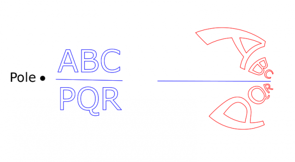
The Pole is where the black dot on the left is. (I put the dot there just to show the location.) Recall that that point would be sent to infinity. Therefore, the points close to the Pole are affected strongly by the transformation. This should explain the result on the right (red). It is as if the letters 'A' and 'P' were the most repelled by the Pole. It is as if the Möbius function would like to throw 'A' and 'P' to somewhere very far away. The other letters are not so close to the pole, hence the effect on them is smaller.
In the next picture I put the Pole right in the middle of the letter 'Q', just to try something wild. (The Pole is not marked this time, and the Base and the Target are set to unvisible.)
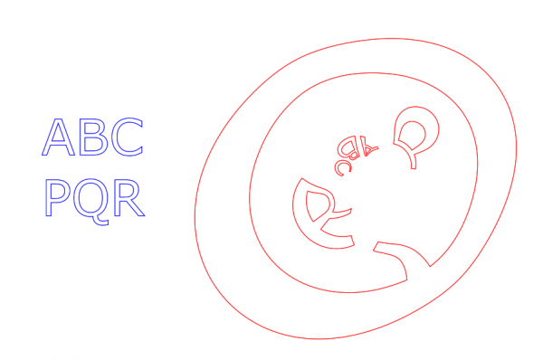
So the Pole is inside the 'Q'. Note that as the result the 'Q' is turned inside out! Even more, the whole plane is turned inside out: Everything that was outside the 'Q', is now crammed inside it, including the other letters. And even more, what was previously inside the 'Q' is now outside it and is stretched to fill the rest of the plane (though we cannot see this effect since there were originally no drawings inside the 'Q').
And all this is done conformally! All angles are preserved. Isn't the Möbius function wonderful!
Posts: 236
Threads: 26
Joined: Mar 2020
Reputation:
29
Gimp version:
Operating system(s): Windows (Vista and later)
07-12-2020, 12:50 PM
(This post was last modified: 07-12-2020, 01:59 PM by Ottia Tuota.)
I made another path transformation plugin. It is based on an idea of my own. But I cannot believe that no predecessors would exist. The idea is so simple.
The link to download the plugin (and all the previous ones) is in post #1. It is a .zip file but contains one big file only. The version is now 0.15.
Better to start with a picture:
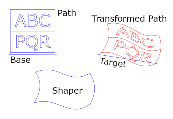
The input paths in this picture are:
- The Path to be transformed (the letters ABCPQR with the frame)
- The Base, a path with 2 anchors
- The Target, a path with 2 anchors
- The Shaper, a curvy quadrilateral consisting of four Bezier arcs (closed, four anchors)
The Shaper is what defines the shape of the transformation. The Base and the Target determine from where to where the mapping goes. You see that the Transformed Path is the original Path but deformed in the shape of the Shaper and moved to the Target.
In the plugin I assumed that the Shaper is a simple curvy quadrilateral covering roughly a rectangular region. Anything else may work ok, or it may give weird results. I also assumed that the edges of the Shaper run roughly: horizontal-vertical-horizontal-vertical, but that is not so necessary to get good results.
The plugin is somewhat similar to the one in post #3. Main differences are:
- This transformation is not conformal.
- The Shaper is made of 4 Bezier arcs (rather than just 1).
- The plugin also allows Base and Target with 4 anchors.
The plugin is based on my own ideas, hence I want to record and share the formulas and a little of how the plugin works internally. I wrote the following pdf. (It is rather long. I hope you allow the old mathematics teacher this little joy of writing mathematics.) Note there especially formula (3). Natural isn't it! (In a mathematician's eyes at least it is.) I don't think that such obvious-looking formula could be new. So, this transformation (formula) may already have some proper name. If so, it would be nice to know it. Lacking a better name, I call it " a map shaped by a Bezier arc quadrilateral".
 transformation_by_16_bezier.pdf
 (Size: 247.04 KB / Downloads: 589)
My plugin transforms paths, but from the formulas somebody more skilled could write a tool for transforming images.
I admit that the results are not always so neat as in the few pictures in this post. The Bernstein polynomials are of degree 3, after all, and they tend to grow fast. So the outcomes are not easy to control, and one has just to go experimenting and trying to learn to use the plugin. I haven't much done that myself since this is quite new and I have a lot of other things to do. If the plugin goes too wild, one can curb the Shaper by the input 'strength'. Another good rule is to place the Base quite close to the Path.
There is another way to use the the plugin: Base and Target may have 4 anchors. This allows the user to have some particular four points mapped onto some other particular four points. A picture:
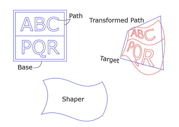
The Path is the text ABCPQR together with the frame. The Base is the slightly bigger square. The Target is the skew quadrilateral. The corner points of the Base are mapped onto the corner points of the Target. The Transformed Path (red) is distorted accordingly. (If I had put the Base exactly at the frame of the Path, the corners of the frame would have been mapped exactly at the corners of the Target. Now there is a little discrepancy.)
A word of warning: When one uses Base and Target with four anchors, the plugin may fail with message like "Hit an infinity". Namely, here the plugin uses projective transformations (I think it is almost the same as Gimp's Perspective transform), and infinities occur quite naturally. So, such failure is not necessarily a sign of a fault with the plugin. If that happens, make changes in the input paths and try again.
Now I explain the other inputs in the GUI of the plugin.
The three 'Permute' inputs you need not touch at all. If the input paths are reasonable, the results should be reasonable. But you can experiment.
- Permute the Base anchors: If the result is not what you expected, you can try to use the Base with its anchors permuted with cyclic rotation and/or reversed. When the Base has 4 anchors, the meaning of the input number is: 0..3 are rotations (0 does nothing) and 4..7 are rotations followed by reversal. When the Base has 2 anchors, there are two alternatives: 0 (or any even number) does nothing, and 1 (or any odd number) causes reversal.
- Permute the Target anchors: This is the same operation for the Target.
- Permute the Shaper anchors: This is the same operation for the Shaper (with always 4 anchors).
- Linearize any straight edges in Shaper: If the Shaper contains a straight edge, its handles may be of zero length, or they may be something else, without any visual difference. But different handle lengths result in different transformations. When the input 'Linearize' is Yes, the plugin internally sets the handles at points 1/3 and 2/3 of the straight edge. This tames a little the transformation which might otherwise be more distorting than desired. (Mathematically: the Bezier function coming from such an edge is made a linear function.)
- Adjust the form of shaping: Experiment.
- Strength of Shaper: Adjust the effect of the curviness of the Shaper. If strength=1, the Shaper is used as is. If strength=0, the Shaper is used with its edges straightened out. If 0<strength<1, the effect is something between.
- Choose algorithm (integer 0..8): The plugin is very slow. By choosing a number >0 the user can make the plugin to use a worse but fast simple algorithm. The idea is to do experimenting with such fast algorithm, and when something good is found, finally draw it with the good but slow algorithm.
Another example to show what the plugin can make from a simple grid using default values but applying different Shapers: The Path is the blue grid. The red figures are the Path transformed by various Shapers. In each case, the Base is set precisely at the bottom edge of the grid (so, two anchors). The Target (not shown) is somewhere else and has two anchors.
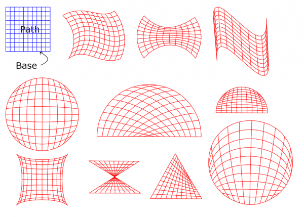
Note in particular the two half circles: the outline is the same but the curved grids inside are different. The secret is that in each the Shaper was a half circle but the anchors on that half circle were placed differently. In other words, the subdivisions of the Shapers into four arcs were different. The same is true for the two circlular cases. And having said that much, I also have to show how the anchors in the Shapers were situated (the handles are not shown):

I hope you enjoy. Any feedback or questions are welcome!
Edit: Deleted one remark. Wrong idea.
Posts: 6,942
Threads: 297
Joined: Oct 2016
Reputation:
605
Gimp version:
Operating system(s): Linux
I find it complicated to use. I don't see much purpose in the "base" and "target". You can make things simpler with one less path. You would have:
1. The source path
2. The "shaper"
3. A rectangle.
The transform maps the rectangle to the shaper. In the nominal use, the rectangle frames the source path. Benefits: the rectangle can be implicit, and can be for instance the bounding box of the source path (max/min x,y of the anchors, or anchors and tangents) or defined by guides, or the selection... See for instance https://www.gimp-forum.net/Thread-ofn-bend-path
What makes the fast algorithm faster?
|


